5 Board Controller API Description
A dedicated microcontroller controls and supervise the fundamental operation of the device.
The main task of this board controller are:
- Device power and reset control
- Main CPU supervision (Heartbeat)
- Sleep mode control
Board Controller Control Functions
The board controller API provides the following functionality. The single commands and respective protocol is stated in chapter 5.3 Board Controller API.
5.1.1 Basic Function
The board controller as a peripheral module provides some board information and control function to the customer application.
- Device version data request
- Supply voltage and current measurement
- UI LED control
In certain cases, the board controller is controlling LED1 directly by its own. See chapter 4.1 LED Indication for more information.
Note:
- Due to a design error on MainBoard HW revision 02 boards the current measurement does not provide usable values.
5.1.2 Reset
The following on board devices and modules can be hard reset if required.
- System reset
- Main CPU reset in terms of an heartbeat supervision
- LTE modem module reset
- Ethernet switch device and USB hub device reset
- Reset peripherals on the extension board (e.g. Auxiliary CPU module, M.2 Modem module)
Note:
- The GPS module hard reset signal is controlled by the main CPU module, see 2.2.3 Main CPU Module GPIOs .
5.1.3 Power Control
For energy saving or reboot purposes the power supply of the following peripherals can controlled.
- WLAN Module
- Modem Module
- Extension module
- independent power control for auxiliary CPU module and M.2 slot
5.1.4 Sleep control
For device power saving reason different device sleep modes are implemented. In sleep mode all but the absolutely required board peripherals are turned off. A wake up from sleep triggers always a system reset.
The device sleep and wakeup behavior is as follows:

- Modem Sleep
- The board controller and the LTE modem module remains operational
- Wake up by a modem ring signal or a enable signal on the ignition pin
- Ignition Sleep
- Only the bord controller remains running
- Wake up only by the ignition signal
5.1.5 Special functions
Those application specific function are implemented.
- SIM card detect toggle
The SIM card detect signal can be toggled even if the SIM card is not physically removed. For monitoring purposes the sim card detect signal is also routed to the main CPU module, see 2.2.3 Main CPU Module GPIOs .
5.2 Board Controller Interface
A serial interface between the main CPU module and the board controller allows the customer application to control the devices basic functionality.
Interface specification:
| Parameter | Value |
|---|---|
| CPU module physical interface | RX SODIMM137 TX SODIMM139 |
| Linux interface | ttymxc1 (/dev/verdin-uart2) |
| Baud rate | 300 bps |
| Data length | 8 bit |
| Stop bit | 1 bit |
| Parity check | no |
Example terminal configuration call:
# stty -F /dev/verdin-uart2 raw 300 cs8 -cstopb -parenb -echo
5.3 Board Controller API
The board controller is controlled by a simple 8bit request-respond protocol. The board controller acknowledges each request with a respond message. The default response is 0x00 but dedicated commands have different responses, see listing below.
Extract from the board controller firmware documentation (FW V2.0):
Parameter:
* An unsigned char representing the command or request code.
* Specific values for `cmd` and their corresponding actions:
* 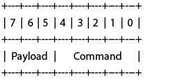
* - Payload as described per Command
* - Commands:
* - 0x00 (SER_LED_CMD_MASK) Select LED 1 (closest to board-middle)
* - 0x01 (SER_LED_CMD_MASK) Select LED 2
* - 0x02 (SER_LED_CMD_MASK) Select LED 3
* - 0x03 (SER_LED_CMD_MASK) Select LED 4 (closest to board-edge)
* o Payload:
* Blinking bit7: 0 - Static, 1 - Blinking
* Color bit6-5: 0 Off, 1 Green, 2 Red, 3 Yellow
* - 0x04 (SER_GET_ADC): Read ADC channel
* o Payload bit6-5:
* 0: Reserved, returns always 0x00
* 1: V_BAT_RTC, multiply result by 12.26 for milli-volts
* 2: SYS_CURRENT, multiply result by 13.95 for milli-amps
* 3: VCAP, multiply result by 36.13 for milli-volts
* 4: VDDSYS, multiply result by 36.13 for milli-volts
* - 0x05 (SER_RESET_MODEM): Reset modem
* - 0x06 (SER_GET_VERSION): Get firmware version
* - 0x07 (SER_GET_REVISION): Get firmware revision
* - 0x08 (SER_SWITCH_WIFI_ONOFF): Switch WiFi on/off
* o Payload bit5: 0 - OFF (default), 1 - ON
* - 0x09 (SER_M2_POWER_ONOFF): Switch M2 Power on/off
* o Payload bit5: 0 - OFF (default), 1 - ON
* - 0x0a (SER_IMX6_POWER_ONOFF): Switch i.MX 6 Power on/off
* o Payload bit5: 0 - OFF (default), 1 - ON
* - 0x0b (SER_ETH_USB_RESET): Reset switch and USB hub
* - 0x0c (SER_EXTENSION_RESET): Reset extension
* - 0x0d (SER_GET_HW_REVISION): Get hardware revision
* - 0x0e (SER_EXECUTE_RESET): Execute system reset
* - 0x0f (SER_HEARTBEAT): Handle heartbeat for watchdog timer
* o Send this command regularly, if not being sent for 10min
* CPU is being reset
* o You can disable this with command SER_HEARTBEAT_DISABLE
* - 0x10 (SER_MODEM_SIM_CD_TOGGLE): Simulate SIM detach/reattach
* - 0x11 (SER_INITIATE_MODEM_SLEEP): Request sleep with modem active
* o Payload bits 5-7: Timeout time in minutes until sleep
* o After this is requested, host has the set time to shut down
* o When timeout time expires everything except
* modem and board controller is powered off.
* o The board can be awakened by the modem ring signal
* or the ignition signal
* o Note: Modem is left powered if this command is being used *
* - 0x12 (SER_INITIATE_IGNITION_SLEEP): Request sleep
* o Payload bits 5-7: Timeout time in minutes until sleep
* o After this is requested, host has the set time to shut down
* o When timeout time expires everything except
* board controller is powered off.
* o The board awakes when the ignition signal goes high
* o Note: It is not recommended to power off modem without
* first shutting it down from software.
* - 0x13 (SER_MODEM_POWER_ONOFF): Switch Modem Power on/off
* o Payload bit5: 0 - OFF, 1 - ON
* o Note: It is not recommended to power off modem without
* first shutting it down from software.
* - 0x14 (SER_GET_IGNITION_LEVEL): Get level of ignition pin
* - 0x15 (SER_HEARTBEAT_DISABLE): Disable the CPU heartbeat supervision
* o Payload bit5: 0 - Supervision enabled (default), 1 - Supervision disabled
* - 0x16-0x1f: Reserved for future use
Return Value:
The return value varies based on the command:
* - 0x00 (SER_LED_CMD_MASK) Select LED 1 (closest to board-middle)
* - 0x01 (SER_LED_CMD_MASK) Select LED 2
* - 0x02 (SER_LED_CMD_MASK) Select LED 3
* - 0x03 (SER_LED_CMD_MASK) Select LED 4 (closest to board-edge)
* o LED requests always return 0x00
* - 0x04 (SER_GET_ADC): Read ADC channel
* o Returns the ADC value, 0x00 in case the selected channel
* is not valid.
* - 0x05 (SER_RESET_MODEM): Reset modem
* o Always returns 0x00
* - 0x06 (SER_GET_VERSION): Get firmware version
* o Return the major version number
* - 0x07 (SER_GET_REVISION): Get firmware revision
* o Return the minor version number
* - 0x08 (SER_SWITCH_WIFI_ONOFF): Switch WiFi on/off
* - 0x09 (SER_M2_POWER_ONOFF): Switch M2 Power on/off
* - 0x0a (SER_IMX6_POWER_ONOFF): Switch i.MX 6 Power on/off
* - 0x0b (SER_ETH_USB_RESET): Reset switch and USB hub
* - 0x0c (SER_EXTENSION_RESET): Reset extension
* o Commands 0x08-0x0c are always returning 0x00
* - 0x0d (SER_GET_HW_REVISION): Get hardware revision
* o Rev. 01 returns 0x02 (Prototypes)
* o Rev. 02 returns 0x00 (Pilot Run)
* - 0x0e (SER_EXECUTE_RESET): Execute system reset
* o No return
* - 0x0f (SER_HEARTBEAT): Handle heartbeat for watchdog timer
* o Always returns 0x00
* - 0x10 (SER_MODEM_SIM_CD_TOGGLE): Simulate SIM detach/reattach
* o Always returns 0x00
* - 0x11 (SER_INITIATE_MODEM_SLEEP): Request sleep without modem
* - 0x12 (SER_INITIATE_IGNITION_SLEEP): Request sleep
* o Both sleep init commands return
* - 0x00 on success
* - 0x01 if there is already a sleep initi pending
* - 0x13 (SER_MODEM_POWER_ONOFF): Switch Modem Power on/off
* - 0x14 (SER_GET_IGNITION_LEVEL): Get level of ignition pin
* o 0x00 if ignition pin is low
* o 0x01 if ignition pin is high
* - 0x15 (SER_HEARTBEAT_DISABLE): Disable the CPU heartbeat supervision
* - Unknown commands return 0xff