2 Device Interface Overview
This section describes the device interface overview and lists the external and internal device interfaces.
2.1 External Interfaces
Front view:

Rear view:

Top view:
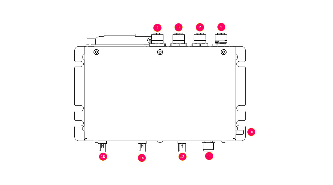
| # | Designation | Description |
|---|---|---|
| 1 | ETH 1 | 1000 BT Ethernet, M12 X-Code 8Pin |
| 2 | ETH 2 | 100BT Ethernet, M12 D-Code 4Pin |
| 3 | ETH 3 | 100BT Ethernet, M12 D-Code 4Pin |
| 4 | ETH 4 | 100BT Ethernet, M12 D-Code 4Pin |
| 5 | Console | Serial terminal port, 115200 Baud |
| 6 | Battery | 3V CR2032, RTC Backup |
| 7 | SD | SD Card Slot |
| 8 | SIM | SIM Card Slot |
| 9 | LED indicators | Device status indicator (LED1, LED2, LED3, LED4) |
| 10 | Earth | Power earth connection, M5 x 9mm |
| 11 | Power Supply / Ignition | Device power supply input and ignition signal, M12 A-Code 4Pin |
| 12 | GPS | GPS module antenna plug, FAKRA C-Code blue |
| 13 | Mobile | LTE module antenna plug, FAKRA D-Code bordeaux |
| 14 | WLAN | WLAN module antenna plug, FAKRA N-Code pastel-green |
2.1.1 Connector Pinout
The following tables states the pin assessment of M12 type power and network connectors. The connectors are described in the view from the device.
M12 A-Code, Power Supply:
| Layout | Pin | Designation | Description |
|---|---|---|---|
 |
1 | + V IN | Positive voltage input |
| 2 | Ignition | Ignition signal input Logic high = enabled (12 -72V) |
|
| 3 | - V IN | Negative voltage input | |
| 4 | N/C | Not connected |
M12 D-Code, 100BT Ethernet:
| Layout | Pin | Designation | Description |
|---|---|---|---|
 |
1 | TX + | Positive differential line TX, yellow |
| 2 | RX + | Positive differential line RX, orange | |
| 3 | TX - | Negative differential line TX, white | |
| 4 | RX - | Negative differential line RX, blue |
M12 X-Code, 1000BT Ethernet:
| Layout | Pin | Designation | Description |
|---|---|---|---|
 |
1 | TXRX A + | Positive differential line TXRX A, white/orange |
| 2 | TXRX A - | Negative differential line TXRX A, orange | |
| 3 | TXRX B + | Positive differential line TXRX B, white/green | |
| 4 | TXRX B - | Negative differential line TXRX B, green | |
| 5 | TXRX D + | Positive differential line TXRX D, white/brown | |
| 6 | TXRX D - | Negative differential line TXRX D, brown | |
| 7 | TXRX C + | Positive differential line TXRX C, white/blue | |
| 8 | TXRX C - | Negative differential line TXRX C, blue |
2.2 Internal Device Interfaces
The internal interfaces between the different functional modules and the current ethernet interface configuration is stated here.
2.2.1 Peripheral Access
Interface and peripheral module access from Linux user space:
| Module | Interface |
|---|---|
| GPS | /dev/verdin-uart1 (ttymxc0) |
| Board-Controller | /dev/verdin-uart2 (ttymxc1) |
| USB-C Konsolenport | /dev/verdin-uart3 (ttymxc2) |
| UART Extension (Konsole i.MX 6) | /dev/verdin-uart4 (ttymxc3) |
| EEPROM 1 (User Data) | /dev/i2c-3 Adresse 0x50 |
| EEPROM 2 (Device Data) | /dev/i2c-3 Adresse 0x51 |
| FRAM | SPI1 CS1 (gpiochip0 5) |
| SD-Karte | /dev/sda |
| Modem | USB Bus001 |
2.2.2 Network interfaces
The device provides the following network interfaces:
| Interface | Description |
|---|---|
| eth0 | Internal connection between Verdin IMX8 CPU module and Switch Chip (do not use) |
| eth1 | Gigabit ethernet port, direct connection with Verdin IMX8 CPU (M12 ETH1) |
| eth2 | 100BT ethernet port, connected to on-board switch chip (M12 ETH2) |
| eth4 | 100BT ethernet port, connected to on-board switch chip (M12 ETh4) |
| eth4 | 100BT ethernet port, connected to on-board switch chip (M12 ETH4) |
| eth_ext | Internal connection between IMX8 CPU module and the auxiliary IMX6 CPU module via on-board switch |
| wwan0 | Mobile data connection via the modem module (need to be activated) |
| wlan0 | WLAN data connection (wlan module hast to be activated) |
Switch can be configured directly in Linux via normal ethernet bridges.
See https://docs.kernel.org/networking/dsa/configuration.html
2.2.3 Main CPU Module GPIOs
The table shows where the GPIOs are connected to the Verdin module (SODIMM pin). These names can be used to find out to which gpiochip/port this is.
Use:
gpiofind "GPIO Name"
gpioset $(gpiofind "GPIO Name")=0/1
| Signal | I/O | Logic | GPIO Name | |
|---|---|---|---|---|
| SPI1 FRAM chip select | O | Neg | SODIMM_210 | SPI bus FRAM device chip select signal |
| GPS reset (from verdin) | O | Neg | SODIMM_222 | Reset of the GPS Module, see [4] |
| GPS time pulse (PPS) | I | - | SODIMM_52 | GPS Time Pulse, see [4] |
| GPS interrupt | I | - | SODIMM_54 | GPS interrupt signal, see [4] |
| Modem Status | I | Pos | SODIMM_56 | LTE Modem status, see [3] (3.1.12.1) |
| Modem Wakeup | I | Pos | SODIMM_58 | Wake up signal, see [3] (3.1.12.4) |
| SIM card detect | I | Neg | SODIMM_60 | SIM card detect signal from SIM slot |
| ETH Switch reset (from verdin) | O | Neg | SODIMM_62 | Signal to reset the ETH switch chip |
| Shutdown (from board cont.) | I | Neg | SODIMM_64 | Board controller indicates to shut down |
| Extension GPIO 1 | I/O | - | SODIMM_66 | Reserved, GPIO on ExtensionBoard |
| Extension GPIO 2 | I/O | - | SODIMM_15 | Reserved, GPIO on ExtensionBoard |
| WL18 CLK (GPIO11) | O | - | SODIMM_218 | WL module clock trigger, see [5] |
| WL18 IRQ | I | - | SODIMM_212 | WL module interrupt signal, see [6], [5] |
| WL18 EN | O | - | SODIMM_216 | WL module enable signal, see [6] |
| IEEE1588 Event Source | O | - | SODIMM_220 | PTP time pulse to ETH switch, see [1] |
| IEEE1588 PPS Sink | I | SODIMM_36 | PTP time pulse from ETH switch, see [1] |
2.3 Network MAC Address and Identification Number
The device has different unique device identification numbers in terms of IP v4 MAC addresses preprogrammed. All unique IDs are accessible in user space.
2.3.1 Main MAC Address and Identification Number
The device main MAC address is stored in a read only section of the device data EEPROM memory. See chapter 4.2.1 Device Data on how to read the MAC address number.
This MAC address number is also used as generic device identification number and printed on to the label.
The OUI of the preprogrammed MAC address belongs to Microchip IEEE address range. Microchip permits the uses of those MAC addresses for customer application. Detailed information can be found here:
www.microchip.com/en-us/products/memory/serial-eeprom/mac-address-and-unique-id-eeproms
If the customer builds and runs its own RAR4000 series device software application, he has to configure the device network interface settings accordingly so that the device network ID meets the data printed on the device label.
2.3.2 Auxiliary MAC Address
A second unique MAC Address is stored in the EEPROM memory intended to store user data. This MAC can used be the customer for more advance network device configuration. For more information on how to retrieve the data see chapter 4.2.2 User Data .
2.3.3 Main CPU MAC Address
The i.MX8 Verdin CPU module has a preconfigured network MAC address. The OUI of this MAC belong to the Toradex address range. The factory set MAC address corresponds with the CPU module identification number.
The MAC address of the CPU module can be configured and changed from user space. For more information see Toradex Knowledge Base:
www.developer.toradex.com/windows-ce/knowledge-base/mac-address
2.3.4 Auxiliary CPU MAC Address
The i.MX6 CPU module has its own factory programmed MAC address. The OUI of this MAC belong to the Phytec IEEE address range. For more information see the phyCore i.MX 6 BSP reference manual.