1 Introduction
This document states how the device can be put in operation and describes the capability and usage of the demo SW image.
1.1 To the Document
- Changes are tracked with the MS Word tool “Track changes”
- Open points are marked in purple
- Authors notes are marked in yellow
1.2 Device Description
RAR4000 is a powerful and rugged Transport / Infrastructure computer platform that offers advanced connectivity in small size and with low power consumption. In addition to its use in rolling stock the RAR units can also be used in general mission critical M2M applications and industrial settings. Care has been taken to ensure that the devices are fault tolerant and can recover from any unwanted operation state. With ultra-wide input voltage range and partially redundant power supplies as well as 4G available on request WiFi GPS and an integrated fully managed Ethernet Switch they can be used in a wide range of applications and environments.
1.2.1 Device Onboard Peripherals:
The following modules and chips are part of the system and provide functionality to the customer application.
MainBoard:
| Function | Designation | Documentation |
|---|---|---|
| Main CPU Module | Toradex Verdin iMX8M Plus IT 1.6GHz 4GB RAM 32GB Flash | Product Page | Datasheet [1] |
| LTE Module | Telit PLS83-W | Product Page | Datasheet |
| GPS Module | u-Blox MAX-M10s | Product Page | Datasheet |
| WLAN Module | Texas Instruments WL1807 | Product Page | Datasheet |
| Switch Chip | Microchip KSZ8565RTXV | Product Page | Datasheet |
| USB Hub | Microchip USB2642 | Product Page | Datasheet |
| EEPROM | Microchip 24AA025E48 | Product Page | Datasheet |
| Temperature Sensor | Texas Instruments TMP75 | Product Page | Datasheet |
| FRAM (optional) | Fujitsu MB85RS256 | Product Page | Datasheet |
IMX6 ExtensionBoard:
| Function | Designation | Documentation |
|---|---|---|
| Auxiliary CPU Module | Phytec phyCore IMX6 Solo 800MHz, 256MB Ram, 512MB Flash | Product Page | Datasheet [1] |
| M.2 Slot | M.2 Key B For auxiliary modem module | n/a |
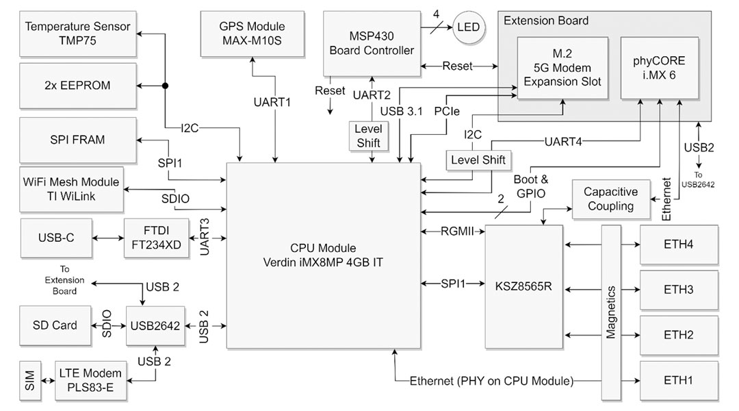
1.2.2 Block Diagram
The detailed block diagram of the RAR4000 with IMX6 ExtensionBoard:
2 Device Interface Overview
This section describes the device interface overview and lists the external and internal device interfaces.
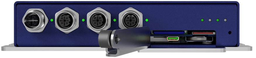
2.1 External Interfaces
Front view:

Rear view:

Top view:
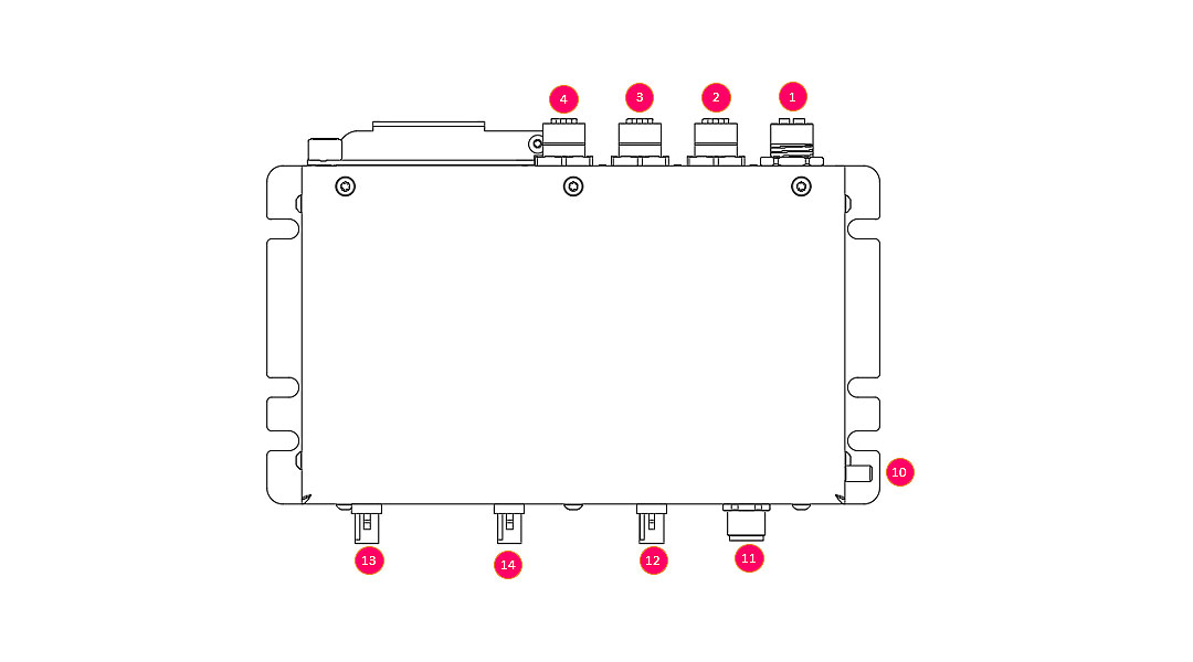
| # | Designation | Description |
|---|---|---|
| 1 | ETH 1 | 1000 BT Ethernet, M12 X-Code 8Pin |
| 2 | ETH 2 | 100BT Ethernet, M12 D-Code 4Pin |
| 3 | ETH 3 | 100BT Ethernet, M12 D-Code 4Pin |
| 4 | ETH 4 | 100BT Ethernet, M12 D-Code 4Pin |
| 5 | Console | Serial terminal port, 115200 Baud |
| 6 | Battery | 3V CR2032, RTC Backup |
| 7 | SD | SD Card Slot |
| 8 | SIM | SIM Card Slot |
| 9 | LED indicators | Device status indicator (LED1, LED2, LED3, LED4) |
| 10 | Earth | Power earth connection, M5 x 9mm |
| 11 | Power Supply / Ignition | Device power supply input and ignition signal, M12 A-Code 4Pin |
| 12 | GPS | GPS module antenna plug, FAKRA C-Code blue |
| 13 | Mobile | LTE module antenna plug, FAKRA D-Code bordeaux |
| 14 | WLAN | WLAN module antenna plug, FAKRA N-Code pastel-green |
2.1.1 Connector Pinout
The following tables states the pin assessment of M12 type power and network connectors. The connectors are described in the view from the device.
M12 A-Code, Power Supply:
| Layout | Pin | Designation | Description |
|---|---|---|---|
 |
1 | + V IN | Positive voltage input |
| 2 | Ignition | Ignition signal input Logic high = enabled (12 -72V) |
|
| 3 | - V IN | Negative voltage input | |
| 4 | N/C | Not connected |
M12 D-Code, 100BT Ethernet:
| Layout | Pin | Designation | Description |
|---|---|---|---|
 |
1 | TX + | Positive differential line TX, yellow |
| 2 | RX + | Positive differential line RX, orange | |
| 3 | TX - | Negative differential line TX, white | |
| 4 | RX - | Negative differential line RX, blue |
M12 X-Code, 1000BT Ethernet:
| Layout | Pin | Designation | Description |
|---|---|---|---|
 |
1 | TXRX A + | Positive differential line TXRX A, white/orange |
| 2 | TXRX A - | Negative differential line TXRX A, orange | |
| 3 | TXRX B + | Positive differential line TXRX B, white/green | |
| 4 | TXRX B - | Negative differential line TXRX B, green | |
| 5 | TXRX D + | Positive differential line TXRX D, white/brown | |
| 6 | TXRX D - | Negative differential line TXRX D, brown | |
| 7 | TXRX C + | Positive differential line TXRX C, white/blue | |
| 8 | TXRX C - | Negative differential line TXRX C, blue |
2.2 Internal Device Interfaces
The internal interfaces between the different functional modules and the current ethernet interface configuration is stated here.
2.2.1 Peripheral Access
Interface and peripheral module access from Linux user space:
| Module | Interface |
|---|---|
| GPS | /dev/verdin-uart1 (ttymxc0) |
| Board-Controller | /dev/verdin-uart2 (ttymxc1) |
| USB-C Konsolenport | /dev/verdin-uart3 (ttymxc2) |
| UART Extension (Konsole i.MX 6) | /dev/verdin-uart4 (ttymxc3) |
| EEPROM 1 (User Data) | /dev/i2c-3 Adresse 0x50 |
| EEPROM 2 (Device Data) | /dev/i2c-3 Adresse 0x51 |
| FRAM | SPI1 CS1 (gpiochip0 5) |
| SD-Karte | /dev/sda |
| Modem | USB Bus001 |
2.2.2 Network interfaces
The device provides the following network interfaces:
| Interface | Description |
|---|---|
| eth0 | Internal connection between Verdin IMX8 CPU module and Switch Chip (do not use) |
| eth1 | Gigabit ethernet port, direct connection with Verdin IMX8 CPU (M12 ETH1) |
| eth2 | 100BT ethernet port, connected to on-board switch chip (M12 ETH2) |
| eth4 | 100BT ethernet port, connected to on-board switch chip (M12 ETh4) |
| eth4 | 100BT ethernet port, connected to on-board switch chip (M12 ETH4) |
| eth_ext | Internal connection between IMX8 CPU module and the auxiliary IMX6 CPU module via on-board switch |
| wwan0 | Mobile data connection via the modem module (need to be activated) |
| wlan0 | WLAN data connection (wlan module hast to be activated) |
Switch can be configured directly in Linux via normal ethernet bridges.
See https://docs.kernel.org/networking/dsa/configuration.html
2.2.3 Main CPU Module GPIOs
The table shows where the GPIOs are connected to the Verdin module (SODIMM pin). These names can be used to find out to which gpiochip/port this is.
Use:
gpiofind "GPIO Name"
gpioset $(gpiofind "GPIO Name")=0/1
| Signal | I/O | Logic | GPIO Name | |
|---|---|---|---|---|
| SPI1 FRAM chip select | O | Neg | SODIMM_210 | SPI bus FRAM device chip select signal |
| GPS reset (from verdin) | O | Neg | SODIMM_222 | Reset of the GPS Module, see [4] |
| GPS time pulse (PPS) | I | - | SODIMM_52 | GPS Time Pulse, see [4] |
| GPS interrupt | I | - | SODIMM_54 | GPS interrupt signal, see [4] |
| Modem Status | I | Pos | SODIMM_56 | LTE Modem status, see [3] (3.1.12.1) |
| Modem Wakeup | I | Pos | SODIMM_58 | Wake up signal, see [3] (3.1.12.4) |
| SIM card detect | I | Neg | SODIMM_60 | SIM card detect signal from SIM slot |
| ETH Switch reset (from verdin) | O | Neg | SODIMM_62 | Signal to reset the ETH switch chip |
| Shutdown (from board cont.) | I | Neg | SODIMM_64 | Board controller indicates to shut down |
| Extension GPIO 1 | I/O | - | SODIMM_66 | Reserved, GPIO on ExtensionBoard |
| Extension GPIO 2 | I/O | - | SODIMM_15 | Reserved, GPIO on ExtensionBoard |
| WL18 CLK (GPIO11) | O | - | SODIMM_218 | WL module clock trigger, see [5] |
| WL18 IRQ | I | - | SODIMM_212 | WL module interrupt signal, see [6], [5] |
| WL18 EN | O | - | SODIMM_216 | WL module enable signal, see [6] |
| IEEE1588 Event Source | O | - | SODIMM_220 | PTP time pulse to ETH switch, see [1] |
| IEEE1588 PPS Sink | I | SODIMM_36 | PTP time pulse from ETH switch, see [1] |
2.3 Network MAC Address and Identification Number
The device has different unique device identification numbers in terms of IP v4 MAC addresses preprogrammed. All unique IDs are accessible in user space.
2.3.1 Main MAC Address and Identification Number
The device main MAC address is stored in a read only section of the device data EEPROM memory. See chapter 4.2.1 Device Data on how to read the MAC address number.
This MAC address number is also used as generic device identification number and printed on to the label.
The OUI of the preprogrammed MAC address belongs to Microchip IEEE address range. Microchip permits the uses of those MAC addresses for customer application. Detailed information can be found here:
www.microchip.com/en-us/products/memory/serial-eeprom/mac-address-and-unique-id-eeproms
If the customer builds and runs its own RAR4000 series device software application, he has to configure the device network interface settings accordingly so that the device network ID meets the data printed on the device label.
2.3.2 Auxiliary MAC Address
A second unique MAC Address is stored in the EEPROM memory intended to store user data. This MAC can used be the customer for more advance network device configuration. For more information on how to retrieve the data see chapter 4.2.2 User Data .
2.3.3 Main CPU MAC Address
The i.MX8 Verdin CPU module has a preconfigured network MAC address. The OUI of this MAC belong to the Toradex address range. The factory set MAC address corresponds with the CPU module identification number.
The MAC address of the CPU module can be configured and changed from user space. For more information see Toradex Knowledge Base:
www.developer.toradex.com/windows-ce/knowledge-base/mac-address
2.3.4 Auxiliary CPU MAC Address
The i.MX6 CPU module has its own factory programmed MAC address. The OUI of this MAC belong to the Phytec IEEE address range. For more information see the phyCore i.MX 6 BSP reference manual.
3 Starting up the device
The device is self-maintained. As soon as the device is powered by the DC Power Connector it is booting up. The MCU controls the different hardware peripherals like CPU, LTE, GNSS or WLAN module.
In the default bootup state the MCU is fully operational and the Linux operating system on the IMX8 CPU module is booted up. The network switch provides its interfaces as network ports to the main CPU module. The GNSS module is powered up and running. All the other modules (LTE, WLAN and auxiliary CPU) are disabled.
The green status LED is blinking, all the other LED indicators are turned off.
3.1 Access to the device
The console interface of Linux operating system running on the IMX8 main CPU module can be accessed ether by one of the network ports or the exposed serial terminal interface.
3.1.1 Serial terminal interface
Even if the device in unpowered a serial interface is provided to the host computer if an USB-C cable is plugged into the USB port located on the service port. By connecting a serial terminal (e.g Putty) to this serial port access to the Linux CLI is established.
Serial port configuration:
- Baud rate: 115200 Baud
- Protocol: 8N1
3.1.2 Network access
All the four ethernet ports can accept an assigned IP address from an DHCP server. Once an IP is assigned an SSH connection can be established (e.g Putty) to get access to the Linux CLI interface.
3.1.3 Loggin in to the demo application
The preconfigured user of the demo application has per default admin rights.
The default user logging is:
Username: root
Password: no password
The test application can be started with the following steps:
- Wait until the test application has been booted and the terminal returns
“verdin-imx8mp-xxxxxxxx login:” - Enter the default user "root” and confirm with “Enter”
- The successful logging is confirmed by string “root@verdin-imx8mp-xxxxxxxx:~#”

- The demo application is ready to work with
3.2 Activate the entire hardware
Not all peripheral modules are activated after start-up. The following peripheral modules are initially ready for operation:
- Bord controller MCU
- Main CPU module (Verdin IMX8)
- Ethernet ports (Switch Chip)
- GPS module
The following peripheral modules must be activated specifically:
- LTE Modem
- WLAN module
- Auxiliary CPU module (IMX6 phyCore)
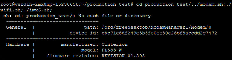
By executing this command line the whole device is active:
root@verdin-imx8mp-xxxxxxxx:~# cd production_test/;./modem.sh;./wifi.sh;./imx6.sh;
e.g.:
4 Device Features
4.1 LED Indication
The demo application does not actively control the LED indication.
The table below shows the LED indication controlled by the bord controller MCU. The LED indicator stats can be overwritten by the application. The MCU ether restores the previous indication state after signaling an action (e.g. modem reset) or triggers a reset (reboot) of the whole device.
Board Controller LED indication:
| Mode / LED | LED1 | LED2 | LED3 | LED4 |
|---|---|---|---|---|
| Device Active (initial state) | Green blinking | / | / |
/ |
| Modem reset ongoing | Red blinking | / | / |
/ |
| Reset button pressed | Red blinking | / | / |
/ |
| Undervoltage detected (ERROR) | Red blinking | / | / |
/ |
| IMX8 heart beat reset | Red single flash | / | / |
/ |
| Device in Sleep Mode | Yellow blinking | / | / |
/ |
4.2 Device and User Data Memory
Beside the eMMC memory on the CPU module and the pluggable SD memory card, the device has dedicated persistent storage for configuration and user data. Those memory section are further described further in this chapter.
Device Data
Factory preprogrammed device data are stored in one of the two I2C EEPROM memories.
This memory section must not be used for user application data, see therefore the user data memory.
The memory can be accessed by the I2C Bus interface, see 6.3 EERPOM Script as example.
EEPROM Device:
| Type: | 24AA025E48T-I/OT |
| Manufacturer | Microchip |
| Size: | 256 Byte |
| Organization | 2 Blocks a 128 Bytes |
| I2C address: | 0x51 |
Memory Map:
| Address [in HEX] | Description | Size [Byte] | Format | ||
|---|---|---|---|---|---|
| 0x00 | Reserved | 250 | TBD | ||
| 0xFA | Device MAC and identification number | 6 |
|
4.2.2 User Data
The RAR4000 series devices provide a dedicated EEPROM memory for storing user applications configuration parameters persistently. This memory section is under full control of the user application. For advanced network device configuration the preprogrammed globally unique MAC address can be used.
If the user application desires more persistent configuration data memory, see section 4.2.3 Extended User Data (optional).
The memory can be accessed by the I2C Bus interface, see 6.3 EERPOM Script as example.
EEPROM Device:
| Type: | 24AA025E48T-I/OT |
| Manufacturer | Microchip |
| Size: | 256 Byte |
| Organization | 2 Blocks a 128 Bytes |
| I2C address: | 0x50 |
Memory Map:
| Address [in HEX] | Description | Size [Byte] | Format | ||
|---|---|---|---|---|---|
| 0x00 | User Configuration Data | 250 | To be defined by the user application | ||
| 0xFA | Device MAC and identification number | 6 |
0xFA 0xFF |
4.2.3 Extended User Data (optional)
The RAR4000 series devices can be assembled on request with an FRAM memory device to extend user configuration data capacity to up to 32k Byte and very short read and write cycles.
EEPROM Device:
| Type: | FRAM |
|
Size: |
32k Byte |
|
Organization |
32768 x 8 Bit with different write protection levels |
|
SPI CS: |
See 2.2.3 Main CPU Module GPIOs |
For more information please contact us.
4.3 RTC Backup Battery
A replaceable clock backup battery can be inserted to maintain the calendar time if the device is unpowered or offline. The current battery voltage level can be measured and read out by the board controller (see 5.3 Board Controller API).
Battery type: 3V Lithium Coin Cell, CR2032
Assembly step resalt
- The battery holder is located in the service port.
- Place the battery with the plus-pole (+) pointing downwards into the battery holder.

5 Board Controller API Description
A dedicated microcontroller controls and supervise the fundamental operation of the device.
The main task of this board controller are:
- Device power and reset control
- Main CPU supervision (Heartbeat)
- Sleep mode control
Board Controller Control Functions
The board controller API provides the following functionality. The single commands and respective protocol is stated in chapter 5.3 Board Controller API.
5.1.1 Basic Function
The board controller as a peripheral module provides some board information and control function to the customer application.
- Device version data request
- Supply voltage and current measurement
- UI LED control
In certain cases, the board controller is controlling LED1 directly by its own. See chapter 4.1 LED Indication for more information.
Note:
- Due to a design error on MainBoard HW revision 02 boards the current measurement does not provide usable values.
5.1.2 Reset
The following on board devices and modules can be hard reset if required.
- System reset
- Main CPU reset in terms of an heartbeat supervision
- LTE modem module reset
- Ethernet switch device and USB hub device reset
- Reset peripherals on the extension board (e.g. Auxiliary CPU module, M.2 Modem module)
Note:
- The GPS module hard reset signal is controlled by the main CPU module, see 2.2.3 Main CPU Module GPIOs .
5.1.3 Power Control
For energy saving or reboot purposes the power supply of the following peripherals can controlled.
- WLAN Module
- Modem Module
- Extension module
- independent power control for auxiliary CPU module and M.2 slot
5.1.4 Sleep control
For device power saving reason different device sleep modes are implemented. In sleep mode all but the absolutely required board peripherals are turned off. A wake up from sleep triggers always a system reset.
The device sleep and wakeup behavior is as follows:

- Modem Sleep
- The board controller and the LTE modem module remains operational
- Wake up by a modem ring signal or a enable signal on the ignition pin
- Ignition Sleep
- Only the bord controller remains running
- Wake up only by the ignition signal
5.1.5 Special functions
Those application specific function are implemented.
- SIM card detect toggle
The SIM card detect signal can be toggled even if the SIM card is not physically removed. For monitoring purposes the sim card detect signal is also routed to the main CPU module, see 2.2.3 Main CPU Module GPIOs .
5.2 Board Controller Interface
A serial interface between the main CPU module and the board controller allows the customer application to control the devices basic functionality.
Interface specification:
| Parameter | Value |
|---|---|
| CPU module physical interface | RX SODIMM137 TX SODIMM139 |
| Linux interface | ttymxc1 (/dev/verdin-uart2) |
| Baud rate | 300 bps |
| Data length | 8 bit |
| Stop bit | 1 bit |
| Parity check | no |
Example terminal configuration call:
# stty -F /dev/verdin-uart2 raw 300 cs8 -cstopb -parenb -echo
5.3 Board Controller API
The board controller is controlled by a simple 8bit request-respond protocol. The board controller acknowledges each request with a respond message. The default response is 0x00 but dedicated commands have different responses, see listing below.
Extract from the board controller firmware documentation (FW V2.0):
Parameter:
* An unsigned char representing the command or request code.
* Specific values for `cmd` and their corresponding actions:
* 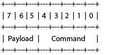
* - Payload as described per Command
* - Commands:
* - 0x00 (SER_LED_CMD_MASK) Select LED 1 (closest to board-middle)
* - 0x01 (SER_LED_CMD_MASK) Select LED 2
* - 0x02 (SER_LED_CMD_MASK) Select LED 3
* - 0x03 (SER_LED_CMD_MASK) Select LED 4 (closest to board-edge)
* o Payload:
* Blinking bit7: 0 - Static, 1 - Blinking
* Color bit6-5: 0 Off, 1 Green, 2 Red, 3 Yellow
* - 0x04 (SER_GET_ADC): Read ADC channel
* o Payload bit6-5:
* 0: Reserved, returns always 0x00
* 1: V_BAT_RTC, multiply result by 12.26 for milli-volts
* 2: SYS_CURRENT, multiply result by 13.95 for milli-amps
* 3: VCAP, multiply result by 36.13 for milli-volts
* 4: VDDSYS, multiply result by 36.13 for milli-volts
* - 0x05 (SER_RESET_MODEM): Reset modem
* - 0x06 (SER_GET_VERSION): Get firmware version
* - 0x07 (SER_GET_REVISION): Get firmware revision
* - 0x08 (SER_SWITCH_WIFI_ONOFF): Switch WiFi on/off
* o Payload bit5: 0 - OFF (default), 1 - ON
* - 0x09 (SER_M2_POWER_ONOFF): Switch M2 Power on/off
* o Payload bit5: 0 - OFF (default), 1 - ON
* - 0x0a (SER_IMX6_POWER_ONOFF): Switch i.MX 6 Power on/off
* o Payload bit5: 0 - OFF (default), 1 - ON
* - 0x0b (SER_ETH_USB_RESET): Reset switch and USB hub
* - 0x0c (SER_EXTENSION_RESET): Reset extension
* - 0x0d (SER_GET_HW_REVISION): Get hardware revision
* - 0x0e (SER_EXECUTE_RESET): Execute system reset
* - 0x0f (SER_HEARTBEAT): Handle heartbeat for watchdog timer
* o Send this command regularly, if not being sent for 10min
* CPU is being reset
* o You can disable this with command SER_HEARTBEAT_DISABLE
* - 0x10 (SER_MODEM_SIM_CD_TOGGLE): Simulate SIM detach/reattach
* - 0x11 (SER_INITIATE_MODEM_SLEEP): Request sleep with modem active
* o Payload bits 5-7: Timeout time in minutes until sleep
* o After this is requested, host has the set time to shut down
* o When timeout time expires everything except
* modem and board controller is powered off.
* o The board can be awakened by the modem ring signal
* or the ignition signal
* o Note: Modem is left powered if this command is being used *
* - 0x12 (SER_INITIATE_IGNITION_SLEEP): Request sleep
* o Payload bits 5-7: Timeout time in minutes until sleep
* o After this is requested, host has the set time to shut down
* o When timeout time expires everything except
* board controller is powered off.
* o The board awakes when the ignition signal goes high
* o Note: It is not recommended to power off modem without
* first shutting it down from software.
* - 0x13 (SER_MODEM_POWER_ONOFF): Switch Modem Power on/off
* o Payload bit5: 0 - OFF, 1 - ON
* o Note: It is not recommended to power off modem without
* first shutting it down from software.
* - 0x14 (SER_GET_IGNITION_LEVEL): Get level of ignition pin
* - 0x15 (SER_HEARTBEAT_DISABLE): Disable the CPU heartbeat supervision
* o Payload bit5: 0 - Supervision enabled (default), 1 - Supervision disabled
* - 0x16-0x1f: Reserved for future use
Return Value:
The return value varies based on the command:
* - 0x00 (SER_LED_CMD_MASK) Select LED 1 (closest to board-middle)
* - 0x01 (SER_LED_CMD_MASK) Select LED 2
* - 0x02 (SER_LED_CMD_MASK) Select LED 3
* - 0x03 (SER_LED_CMD_MASK) Select LED 4 (closest to board-edge)
* o LED requests always return 0x00
* - 0x04 (SER_GET_ADC): Read ADC channel
* o Returns the ADC value, 0x00 in case the selected channel
* is not valid.
* - 0x05 (SER_RESET_MODEM): Reset modem
* o Always returns 0x00
* - 0x06 (SER_GET_VERSION): Get firmware version
* o Return the major version number
* - 0x07 (SER_GET_REVISION): Get firmware revision
* o Return the minor version number
* - 0x08 (SER_SWITCH_WIFI_ONOFF): Switch WiFi on/off
* - 0x09 (SER_M2_POWER_ONOFF): Switch M2 Power on/off
* - 0x0a (SER_IMX6_POWER_ONOFF): Switch i.MX 6 Power on/off
* - 0x0b (SER_ETH_USB_RESET): Reset switch and USB hub
* - 0x0c (SER_EXTENSION_RESET): Reset extension
* o Commands 0x08-0x0c are always returning 0x00
* - 0x0d (SER_GET_HW_REVISION): Get hardware revision
* o Rev. 01 returns 0x02 (Prototypes)
* o Rev. 02 returns 0x00 (Pilot Run)
* - 0x0e (SER_EXECUTE_RESET): Execute system reset
* o No return
* - 0x0f (SER_HEARTBEAT): Handle heartbeat for watchdog timer
* o Always returns 0x00
* - 0x10 (SER_MODEM_SIM_CD_TOGGLE): Simulate SIM detach/reattach
* o Always returns 0x00
* - 0x11 (SER_INITIATE_MODEM_SLEEP): Request sleep without modem
* - 0x12 (SER_INITIATE_IGNITION_SLEEP): Request sleep
* o Both sleep init commands return
* - 0x00 on success
* - 0x01 if there is already a sleep initi pending
* - 0x13 (SER_MODEM_POWER_ONOFF): Switch Modem Power on/off
* - 0x14 (SER_GET_IGNITION_LEVEL): Get level of ignition pin
* o 0x00 if ignition pin is low
* o 0x01 if ignition pin is high
* - 0x15 (SER_HEARTBEAT_DISABLE): Disable the CPU heartbeat supervision
* - Unknown commands return 0xff
6 Device Test Scripts
This chapter describes the different scripts (Bash scripts) develop to support testing of the different peripherals of the device.
6.1 General information to the scripts
The scripts do not evaluate the tests result itself. The test result must be evaluated on the controlling test system. But the test scripts initialize and controls the peripheral modules so that they run in its standard operation mode. By executing the scripts display status and device health data.
6.1.1 Test script location
The test scripts are located on the following path:
/home/root/production_test/
To run the test script, navigate to the "production_test" folder after logging in with the following instruction:
root@verdin-imx8mp-xxxxxxxx:~# cd production_test
Corresponding console output:

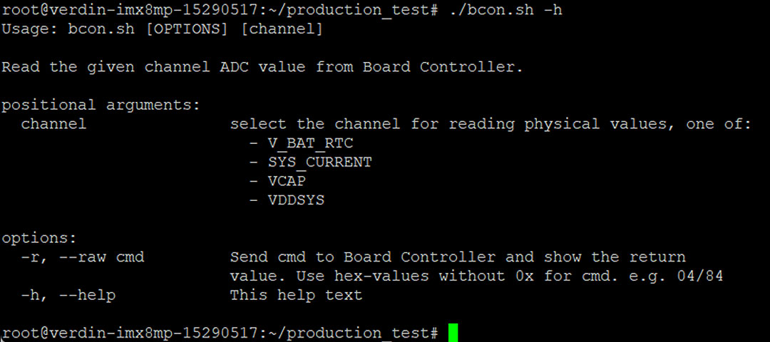
6.1.2 Test script help
Each test script has a brief usage description. To show the help text run the script with the argument “-h”.
Generic call:
root@verdin-imx8mp-xxxxxxxx: production_test # ./<script>.sh -h
e.g:
6.2 Board Controller Script
Test Script:
- bcon.sh
Description:
The scripts initializes the serial communication with the board controller (MSP430 MCU) and enables to send commands. The respond from the board controller is displayed in the terminal.
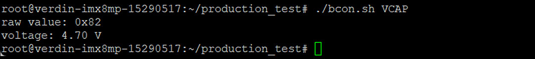
Usage:
- Request the current voltage levels monitored by the MCU. The response from the MCU is preprocessed from the script and displayed in a readable format.
instruction:
./bcon.sh [channel]
channel:- V_BAT_RTC coin cell backup battery voltage level
- VCAP super cap voltage level
- VDDSYS system main voltage level
- Send any command to the board controller.
instruction:
./bcon.sh -r [cmd]
cmd:- The board controller command as hex code. But do not send the “0x” only the number. See the board controller command listing in chapter 5.3.
e.g. Set LED3 green blinking (0b10100010 = 0xa2) :
./bcon.sh -r a2
- The board controller command as hex code. But do not send the “0x” only the number. See the board controller command listing in chapter 5.3.
Example:
6.3 EERPOM Script
Test Script:
- eeprom.sh
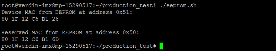
Description:
With that script the MAC addresses stored in the two EEPROM devices are retrieved and displayed in the terminal.
Usage:
- Run the script and the stored MAC addresses are displayed
./eeprom.sh
Example:
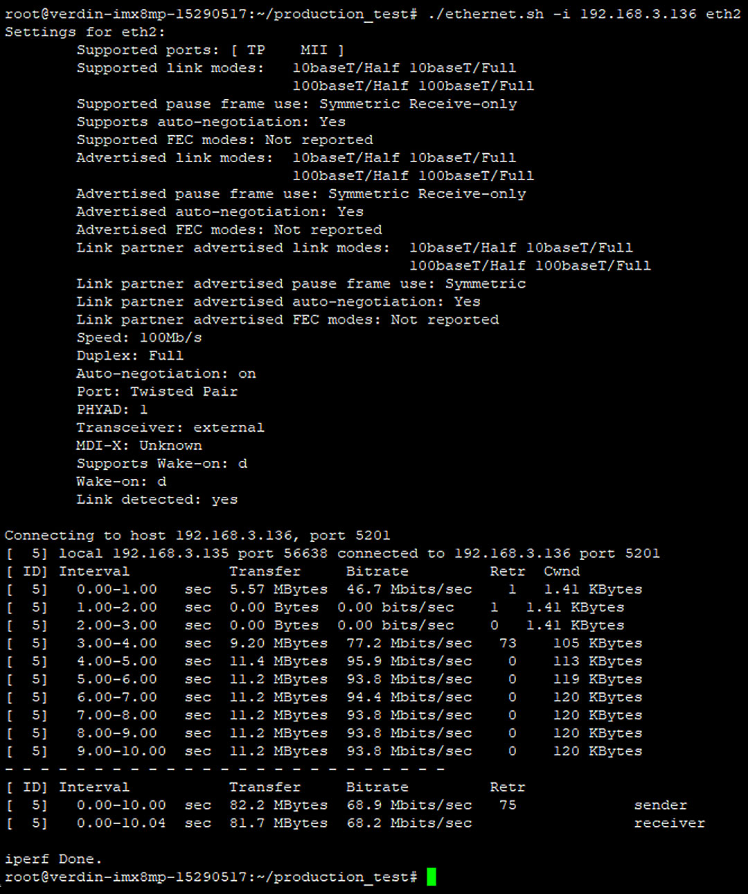
6.4 Ethernet Ports Test Script
Test Script:
- Etherent.sh
Description:
That script encapsulate different networking tools. It provides a simple access to display the current interface configuration and states and executes a bandwidth test on a specific interface.
For the bandwidth test an iperf server as counterpart has to be running on a host with an known IP address. The default IP will be 192.168.1.1, but a customer IP can be set.
Usage:
- Display current ethernet port state. If an iperf server is reachable on 192.168.1.1 the result of the bandwidth test is displayed too.
./ethernet.sh [port]
port:
eth1 Gigabit Ethernet, port 1
eth2 100B/T Ethernet, port 2
eth3 100B/T Ethernet, port 3
eth4 100B/T Ethernet, port 4
eth_ext internal connection to auxiliary CPU (see imx6.sh for activation the module)
- To connect an iperf server with a different IP use the argument “-i <IP>” before the port.
e.g. ./ethernent.sh -i 192.168.178.100 eth1
Example:
6.4.1 Using in Test
The scrip is meant to support the following function test cases:
- DT-TC-F-12 Ethernet Port 1 Functionality
- DT-TC-F-13 Ethernet Port 2 Functionality
- DT-TC-F-14 Ethernet Port 3 Functionality
- DT-TC-F-15 Ethernet Port 4 Functionality
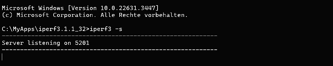
6.4.2 Iperf server
Ethernet transmission test are performed by the use of the CLI bandwidth measurement tool iperf. Iperf can run on Linux, Windows and other operating systems. See https://iperf.fr/ for more information about the iperf framework.
To start an Iperf server use the following cli command on the connected host computer:
iperf3 -s
e.g:
The tool can be tests by starting a iperf client and run a test on the RAR4000 device. Use therefore the following cli command:
Iperf3 -c <Ip Address of the Server>
e.g.

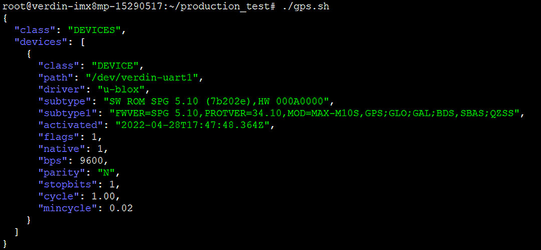
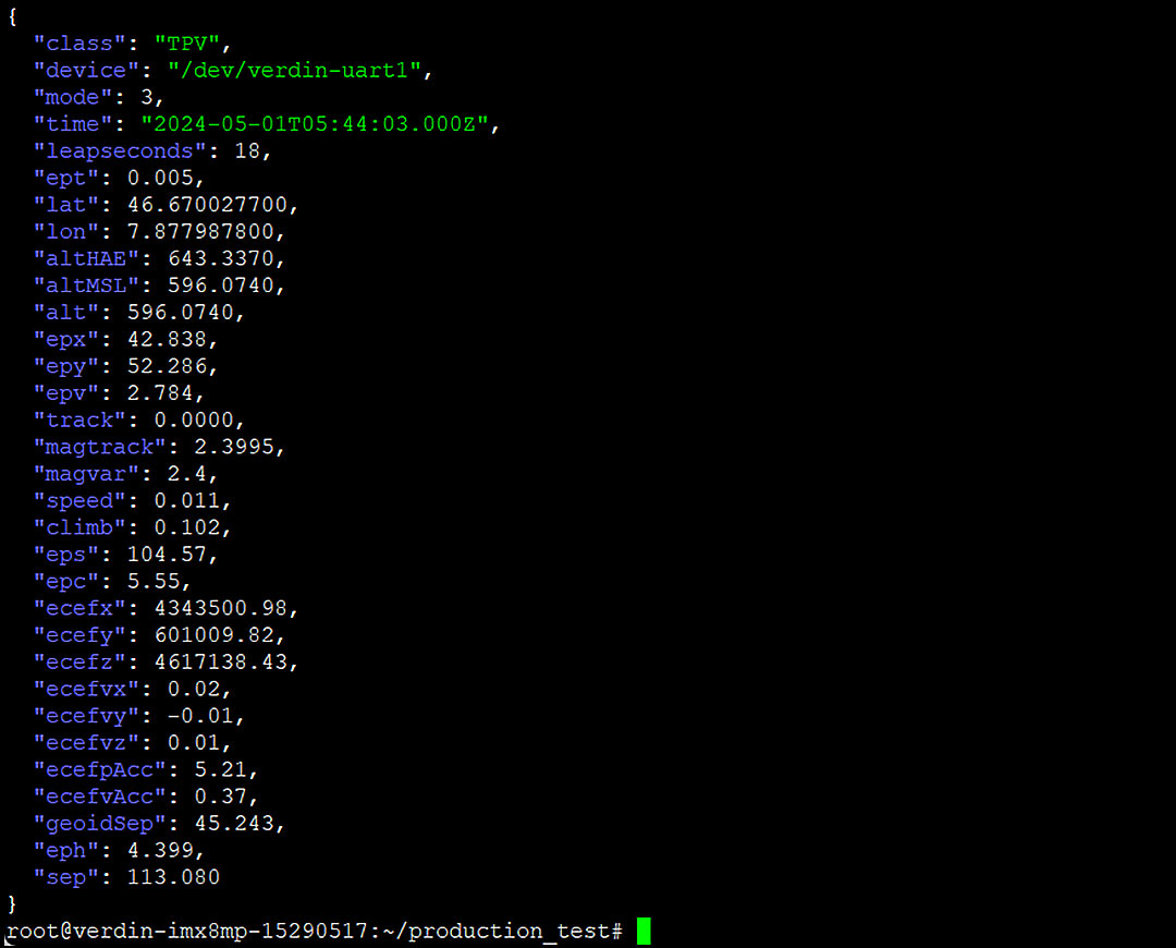
6.5 GPS Script
Test Script:
- gps.sh
Description:
That script initializes the GPS Module an displays module status and configuration data. If a position fix occurred the location data are displayed as well.
Usage:
- That script has no functional parameters. The GPS data are displayed by:
./gps.sh
Example:
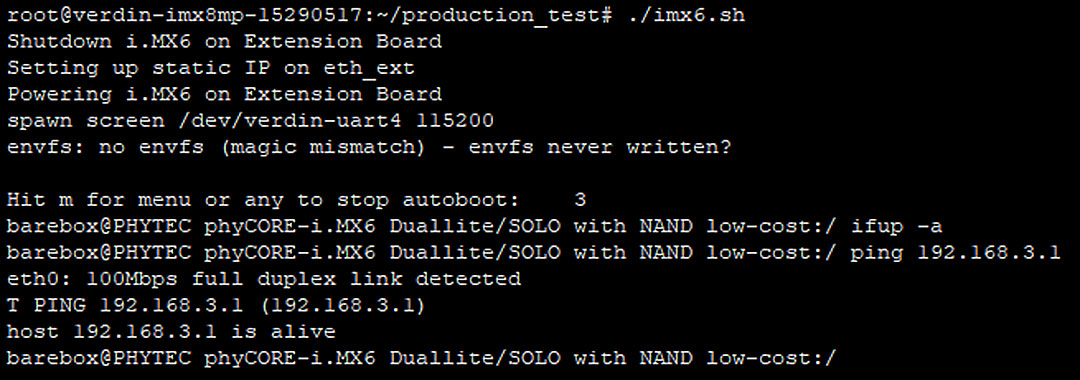
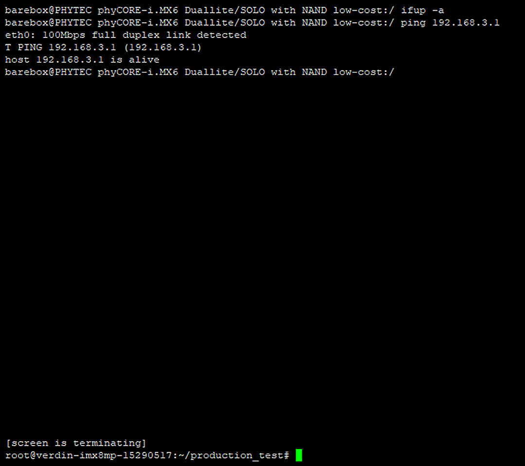
6.6 Auxiliary CPU Module Script
Test Script:
- Imx6.sh
Description:
By calling that script the imx6 extension board is enabled and communication through the serial and ethernet interface is established.
Usage:
- That script has no functional parameters. By executing it the communication status is displayed on the terminal. When the script terminates the extension board remains powered up. To turn off the extension module power send the corresponding board controller command (see 6.2 Board Controller Script).
./imx6.sh
Example:
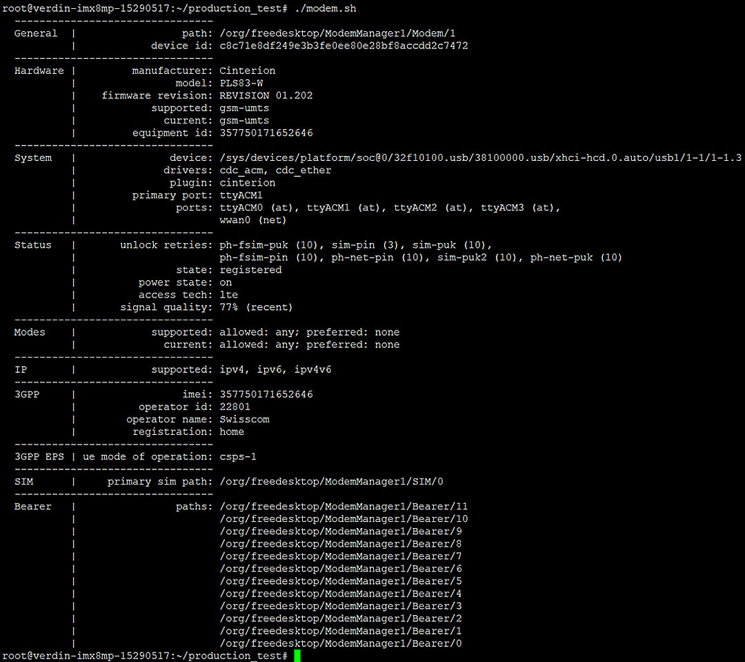
6.7 Modem Script
Test Script:
- modem.sh
Description:
That script initializes the modem module. If a SIM card is present a mobile connection is established. The current operation status of the modem is displayed.
Usage:
- That script has no functional parameters. To enable the modem module and show the status in the terminal call:
./modem.sh
Example:
6.8 SD Card Scripts
Test Script:
- sdcard_write.sh
- sdcard_read.sh
Description:
With those script a file write and read action on the SD card can be performed. A dummy file with a known MD5 hash is stored on the SD card. The corresponding dummy file can be read back and the MD5 hash is checked. For better control the SD card write and read action are separated in two scripts.
Usage:
- To generate a dummy file and write that onto the SD card execute the following command. The script has no functional parameter. The return value on the terminal is the MD5 hash and file name of the stored file.
./sdcard_write.sh - To read back and do a file corruption check call the following command with the file name returned by the sdcard_write.sh script as argument.
./sdcard_read.sh <fileName>
Example:

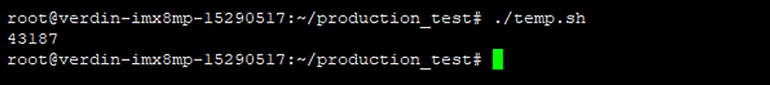
6.9 Temperature Sensor Script
Test Script:
- temp.sh
Description:
The script read the current temperature out of the temperature sensor on the I2C bus and displays the value formatted in milli-degrees Celsius on the terminal.
Usage:
- That script has no functional parameters. To retrieve the current temperature call:
./temp.sh
Example:
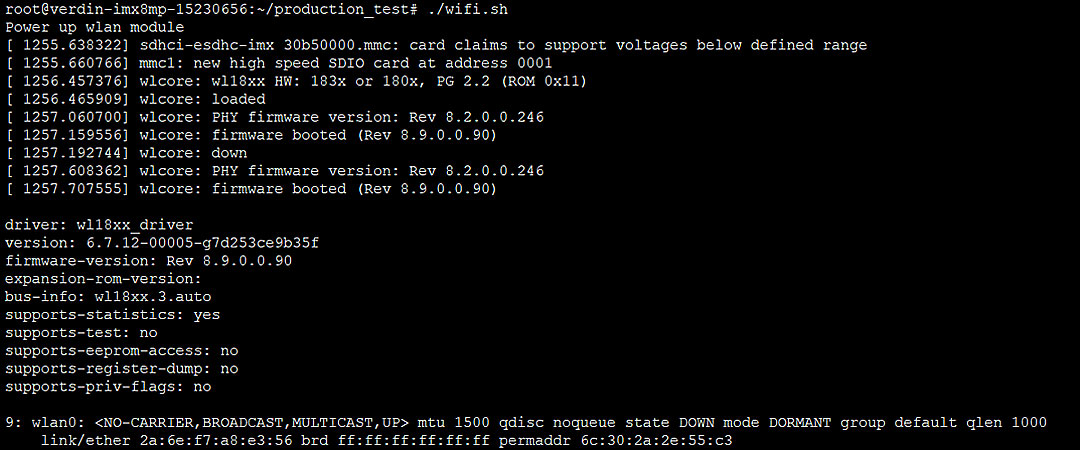
6.10 WLAN Module Script
Test Script:
- wifi.sh
Description:
The script controls the WLAN module power supply and initialization. Depending on the arguments the WLAN module can be enabled or disabled or a WLAN connection can be established.
Usage:
- To enable the WLAN module call the script without an argument.
./wifi.sh - To disable the WLAN module use the argument “-o”:
./wifi.sh -o - To establish a WLAN connection with an nearby access point use the “-c” argument. The GUI like interface from the tool “nmtui” is opening. Navigate to “Acticate a connection” and select an SSID in the section “Wi-Fi”. See the nmtui how to for further help.
./wifi.sh -c
Example:
7 Appendix
7.1 References
| No. | Document title | Version | Comments |
|---|---|---|---|
| [1] | Verdin iMX8M Plus V1.1 datasheet | V1.1 | Main CPU Module Datasheet |
| [2] | TC_PLSx3-W_AT_Command_Set_User_Guide_01.202_r0.pdf | Rev0 | Modem AT Commands |
| [3] | TC_PLSx3_W-EP_Hardware_Interface_Description_User_Guide_r0.pdf | Rev0 | Modem Integration Manual |
| [4] | MAX-M10S Integration Manual | R04 | GPS Manual |
| [5] | Precise Time Synchronization Over WLAN | n/a | WiLink App Note |
| [6] | WiLink8™ Getting Started Guide | n/a | WiLink user guide |
7.2 Terms/Acronyms
The below terms are used as examples, please add/remove any terms relevant to the document.
| TERM/ACRONYM | DEFINITION |
|---|---|
| N/A | Not Applicable |
| PCB | Printed Circuit Board |
| PCBA | Printed Circuit Board Assembled |
| SOP | Standard Operating Procedure |
| TBD | To Be Determined |
7.3 Document Change History
| Version Number | Date | Contributor | Description |
|---|---|---|---|
| V1.0 | 06.05.2024 | SvB | Initial version |
| V1.1 | 03.06.2024 | SvB | - Device Description extended - Board Controller API update - Device overview updated - CPU GPIO description updated |
| V1.2 | 14.06.2024 | SvB | - MAC address chapter added - Data Memory chapter added - Document restructuring |